wp 0x2000,f,w
and then just hitting F5 a couple of times when the watch point triggers, or as in my case, temporary instrument the VIA driver with some proper printouts. Then it is just to decode the bytes written to see what it is up to:

This reveals a lot how the PCB are designed but for now we are just interested in the interrupts as the code seems to be waiting in a tight loop for something to end up in the RAM area, most probably delivered by an interrupt. The last line gives us a clue what interrupt that might be, the Timer 2 interrupt is enabled, we just need to hook it up to the CPU and see where it takes us.
By pressing F7 in the MAME debugger it will execute the ROM until an interrupt happens, and indeed it stops immediately

0x79F8 is indeed the right vector. Now if we set a breakpoint after the tight loop we identified prior enabling the interrupts, let's see what happens.

Hmm, it doesn't trigger. Lets fake input via the RAM location at 0x30 through the memory window (Ctl-M)

Click at the low nibble of the memory location first because the high seems reset all bits set faster than the editor can zero them, and voila!
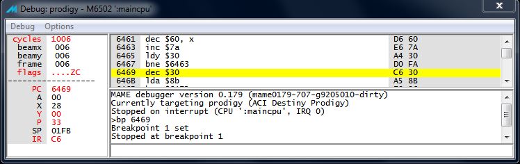
It obviously hits the bp but more important is that the interrupt routine seems fiddling with the 0x30 as well. Next step is to examine the interrupt routine and discover the port usage, mañana! Next->
Inga kommentarer:
Skicka en kommentar